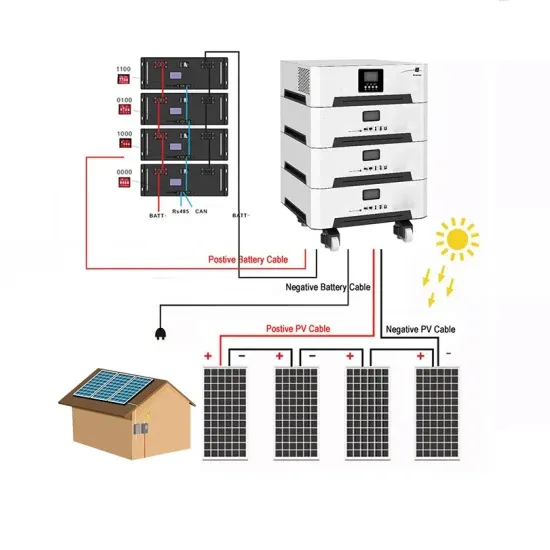
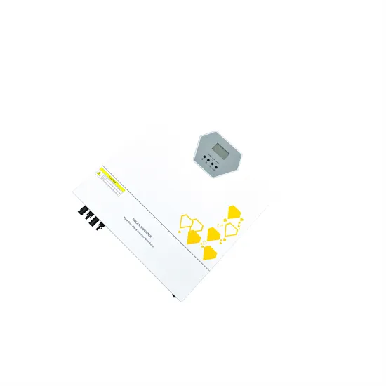
A high-efficiency, three-phase, solar photovoltaic (PV) inverter is presented that has low ground current and is suitable for direct connection to the low voltage (LV) grid. The proposed topology includes a three-phase, two
high efficiency of the inverter circuit, and the high-frequency-free ground loop voltage. Besides the high efficiency inverter circuit, the grid connection function is also the essential part of the PV
The National Electric Code allows for a few different ways to interconnect PV systems to utility systems. In two editions of Code Corner, Ryan Mayfield with Mayfield Renewables, explains busbar, load side
The auxiliary ZVT circuit in the boost stage enables the switching node current to flow through an auxiliary inductor and a transistor placed across the main inductor during complementary device turn OFF, thus ensuring zero
CC operating voltage of control circuit v d diode voltage V D DC value of source voltage v drop voltage drop due to the R DS;on and a resistance of a primary v DS drain-source voltage V e e
The different types of PV inverter topologies for central, string, multi-string, and micro architectures are reviewed. These PV inverters are further classified and analysed by a number of conversion stages, presence of
This paper presents a novel integrated single-phase inverter with both high step-up ratio and buck-boost capabilities for low-voltage alternative energy source applications. An
730 Y. Hou, S. Sun, and E. Li 2.2.4 Each Output Winding Transformer primary winding turns formula 1.2 4 10 1 8 max × × = BfS V N i (3) Where s is the core cross-sectional area, unit of
Figure 8. In a micro solar inverter, we need auxiliary power that can output multiple voltages to A/D sample circuits, drive circuits, MCU controller, and so forth. On the other hand, the auxiliary power must be completely isolated from primary side to secondary side.
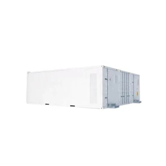
By using a reliable method, a cost-effective system has to be developed to integrate PV systems with the present power grid . Using next-generation semiconductor devices made of silicon carbide (SiC), efficiencies for PV inverters of over 99% are reported .
However, there is an area in the system that requires attention; PV combiners and inverters need low voltage isolated power for monitoring and control derived from the 1,500-V line and small dc-dc converters that operate at these levels are not common.
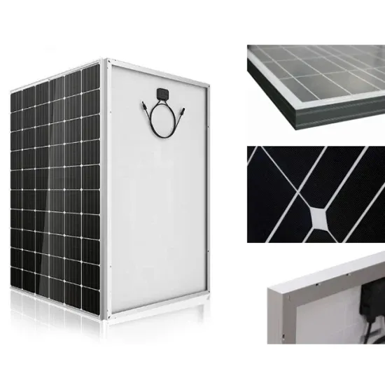
Photovoltaic systems are continually evolving to improve their efficiency and financial viability. One trend is to move to larger strings of cells giving higher dc voltages to be converted to ac voltage for the grid. Cost savings result but auxiliary power supplies for monitoring and control need to accept these higher voltages as inputs.
PV central inverter classification For the usage of electric drives, first, in line-commutated inverters were used ranging in several kilowatts. Then after PV applications, self-commutated inverters are preferred. Voltage source inverter (VSI), Fig. 7a, is one of the traditional configurations of inverters that are connected to a power grid.
The inverter state machine then sequences to checking for DC voltage. To feed current into the grid the DC voltage (which in case of PV inverters is provided from the panel or panel plus some conditioning circuit), it must be greater than the peak of the AC voltage connected at the output of the inverter.