inverter (VSI) uses the topology, which has a characteristic that the average output voltage is always lower than the input dc voltage [2]. Thus if an output voltage higher than the input one

to deal with the number of input sources was to monitor AC output power parameters instead of DC input measurements [8]. Traditional multilevel inverters include cascaded H-bridge
The different types of PV inverter topologies for central, string, multi-string, and micro architectures are reviewed. These PV inverters are further classified and analysed by a number of conversion stages, presence of
The diagram also illustrates the communication interface of the micro inverter, which allows for remote monitoring and control of the system. In a typical micro inverter diagram, each solar
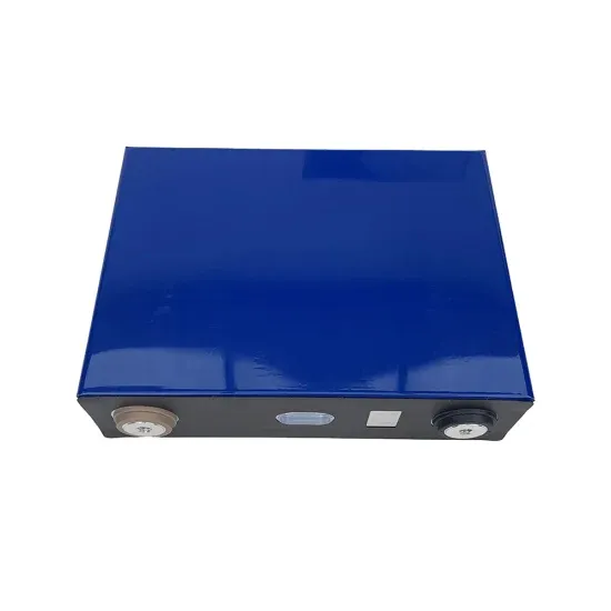
Figure 2 shows the block diagram of a starting inverter with the DC/AC stage marked in red. The rail voltages are around 600V to 1,200V, particularly in string and central inverters, making
large number of solar photovoltaic (PV) power plants are being installed all over the world. As the penetration of this PV plant rose, the interface with the grid may cause various of issues. For
Grid-tied inverters are used in solar power systems to convert the DC power generated by solar panels into AC power, which can be fed into the main grid for consumption or sold back to the utility company. The grid connection allows
In conclusion, the solar panel and inverter connection diagram demonstrates the flow of power from the solar panel to the inverter and further distribution to the electrical panel of a building. This connection allows for the utilization of solar
Download scientific diagram | Block diagram of the proposed grid-connected PV inverter system based on interleaved DCM flyback converter topology. from publication: An Interleaved High
In string inverter systems, the combined DC output of the entire solar panel array is transmitted to the solar inverter or charge controller (for off-grid and hybrid solar systems). The solar inverter converts DC to alternating current (AC or “household” power) for use in your home.
By using a reliable method, a cost-effective system has to be developed to integrate PV systems with the present power grid . Using next-generation semiconductor devices made of silicon carbide (SiC), efficiencies for PV inverters of over 99% are reported .
The nominal input voltage is 36 V DC. Therefore, one solar panel with an output voltage of 36 V, or two solar panels each of 18 V connected in series can be used as the power source for the inverter. For demonstration purposes, the nominal output power of the solar panels can vary from about 50 W up to 200 W per panel.
Discover ST's solutions and ICs for your string or central solar inverter system design, including SiC MOSFETs, IGBTs, power modules, microcontrollers and connectivity solutions.
The main task for this solar panel inverter demo is to present the MPPT feature. For this reason the DC-bus voltage low limit is moved to a low level, about 25 V AC. It is possible to show the output power variation from the solar panel through its dependence on rapidly changing illumination conditions.
PV central inverter classification For the usage of electric drives, first, in line-commutated inverters were used ranging in several kilowatts. Then after PV applications, self-commutated inverters are preferred. Voltage source inverter (VSI), Fig. 7a, is one of the traditional configurations of inverters that are connected to a power grid.