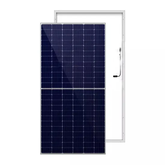
Solar Module Cell: The solar cell is a two-terminal device. One is positive (anode) and the other is negative (cathode). A solar cell arrangement is known as solar module or solar panel where solar panel arrangement is known as

Practically speaking, when useable area is limited, a 22% efficient 300W solar panel could take up most of the available space, limiting the room for future panels and increasing the complexity
Step by step PV Panel installation tutorials with Batteries, UPS (Inverter) and load calculation All about Solar Panel Wiring & Installation Diagrams. Step by step PV Panel installation tutorials with Batteries, UPS (Inverter) and load
Schematic for Wiring Solar Panels in Series. Wiring solar panels in series (plus to minus) will increase the volts, but leave the amps the same. For example, wiring two 18V solar panels together as shown will increase the output from 18V to
A solar panel wiring diagram (also known as a solar panel schematic) is a technical sketch detailing what equipment you need for a solar system as well as how everything should connect together. There''s no such
6. The solar panel mounts will be installed. 7. The professionals will install the solar panels. 8. The solar panels will then be wired in (the house''s electricity will be turned off at this point) 9. The solar panels will be connected
enhance the safety and system performance of the solar PV system installations by considering exemplary practices and innovative technologies identified at the time of preparation and
On-grid solar panel wiring diagram. In this PV system wiring diagram, the panels are series wired. On-grid systems need DC and AC disconnects in case power has to be shut off immediately. Solar combiner box
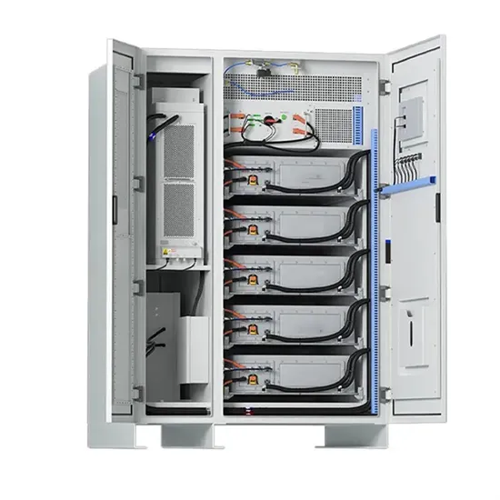
At the heart of every solar energy system lies the solar panel wiring diagram, a blueprint that maps out the connections between various components such as solar panels, inverters, charge controllers, batteries, and electrical wiring.

There are two main methods used in on-grid solar system wiring diagrams to connect solar panels to the grid. Load-Side Connection. Load-side connections are less complicated and cheaper as the PV system is
Voltage, current, wattage, and power are key electrical terms for solar panel wiring. Series wiring increases voltage, parallel wiring increases current. Bypass diodes prevent power loss in shaded panels. Consider system requirements and electrical characteristics for optimal wiring.
Wiring solar panels together can be done with pre-installed wires at the modules, but extending the wiring to the inverter or service panel requires selecting the right wire. For rooftop PV installations, you can use the PV wire, known in Europe as TUV PV Wire or EN 50618 solar cable standard.
A solar panel wiring diagram (also known as a solar panel schematic) is a technical sketch detailing what equipment you need for a solar system as well as how everything should connect together. There’s no such thing as a single correct diagram — several wiring configurations can produce the same result.
These terms form the backbone of solar panel wiring and assist in determining the optimal configuration for any given solar power system. Solar panel wiring, commonly referred to as stringing, involves the connection of multiple solar panels to consolidate their output and integrate it into a home’s electrical system or a battery for storage.
Solar connectors can be used to connect solar panels in series, parallel, or series-parallel. Installing them in series is quite simple while installing them in parallel requires an additional component. To connect solar panels in series you just plug the positive connector of a PV module into the negative connector of the next module.
Most modern photovoltaic systems for residential or portable use don’t actually require much “wiring.” At least not in the traditional sense of soldering circuits together. The majority of solar panels and balance of system components use standardized connectors and cables, such as the Universal Solar Connector.