The GSE Integration system is used to install modules on all types of roofing, (curved tiles, mechanical, flat, slates), on new buildings or buildings being renovated. The system may be

*T-shaped silicone/EPDM rubber seal strip is used for solar photovoltaic panels. It has great heat resistance. Silicone rubber extrusion seal has excellent chemical and physical property, high
Overall, a solar panel diagram with explanation PDF is a valuable resource for understanding the functionality and components of a solar panel system. It provides a visual aid for anyone interested in harnessing solar energy and can
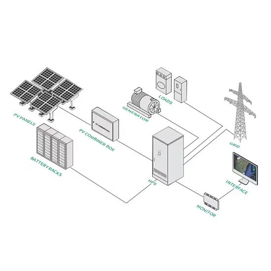
In this article, we will discuss the basic wiring diagram for solar panel installation, including the components and steps involved. Before diving into the wiring diagram, it is important to understand the key components of a solar panel
The purpose of sealing strips is to reduce the effect of the bundle bypass stream that flows around the outside of the tube bundle. They are usually thin strips that fit into slots in the baffles and extend outward toward the shell wall to block the
Install the lead replacement across the top flashing pieces, approximately 50mm from the top of the panels. Remove the backing and dressing it in place as you move across. Fold any excess down over the top of the system. Next we will
When panels produce excess solar power, the net metering allows it to transport to the utility grid, rewarding energy credit in exchange. It is where the output of the solar inverter gets attached. From the AC breaker
First things first, let''s strip back the insulation. I''m using the shears from the kit, but if you''re more comfortable with wire strippers, go for it. Just match them up to the correct

This allows ''net metering'' to take place. In a net metering situation, people are able to sell back to their utility company the excess electricity produced by their solar panel installation. Solar Panel Wiring Diagram. The best way to prepare
Make cuts on the attach angle at the position of the GSE panel corrugations. Assemble the top flashing with the junction and the corner pieces. Apply a seal joint at each junction between 2 pieces. Cut the corner flashing in two distinct pieces. Adjust the height of the corner flashing by overlapping the two pieces.
PLACING A MODuLE1/ Power off the PV INSTALLATION.2/ Remove the clamps from the panel to be replaced.3/ Disconnect the earthing connection and disconnect it from the string. 4/ Take out the panel that needs to be changed and replace it with the new one. 5/ Connect the new panel to the earth a ct it to the string. 6/ pu
Make cuts on the attach angle at the position of the GSE panel corrugations. 3 Place the top junction flashing, having applied beforehand two PU glue joints on the covered top flashing area. The connecting piece must overlap with the top flashing with at least 100 mm. The gap between the top flashings should not exceed 160 mm.
The installer is responsible for ensuring that the building and building structures are capable of withstanding the additional loads and forces generated as a result of installing the PV system. For domestic dwellings, it is recommended that a structural engineering assessment is completed.
Labels relating to the PV system must be placed on the switchboard to which the PV system is directly connected. If the PV system is directly connected to a distribution board, additional labels must also be placed on the main switchboard and all intermediate distribution boards.
BOTTOM: the butyl strip of 10cm is laid on the tiles. When installing all the way to the eaves, the PV field can be connected directly to the gutter with a waterproofing strip or a drip flashing. Assemble the other half-frames laterally thanks to the ergot and vertically. Fix them the same way than described in 1.