During the shading analysis, you can use various tools such as sun-path diagrams or shading simulation software to identify potential obstacles and assess their impact on solar panels throughout the year. An ideal site for
A single-line diagram, often included in a PV plan set, shows the electrical connections, including solar panels, inverters, solar storage batteries, and other essential components. These technical drawings
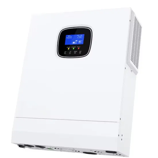
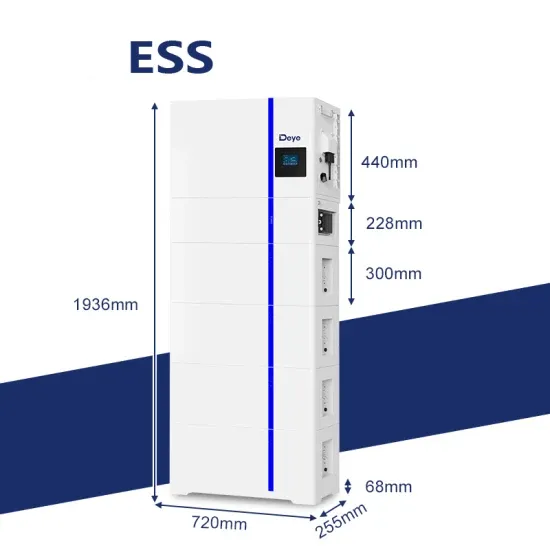
48V battery systems offer numerous benefits compared to lower voltage systems, including more solar power per MPPT, which results in far greater solar capacity per MPPT in DC-coupled systems. Moreover, the

• The fire rating of a Trina Solar PV module is valid only when mounted in the manner specified in the mechanical mounting instructions of this installation manual. • The module is considered to
Learn how to wire a 12V solar panel system with this straightforward wiring diagram and step-by-step guide. Wiring a 12V solar panel typically involves connecting the positive and negative
As we can see, those 60-cell, 72-cell, and 96-cell solar panel dimensions are a bit theoretical. These are the practical solar panel dimensions by wattage from solar panels that are actually
Practically speaking, when useable area is limited, a 22% efficient 300W solar panel could take up most of the available space, limiting the room for future panels and increasing the complexity
When contemplating the addition of solar panels to your roof, the dimensions and effectiveness of these panels are crucial aspects to keep in mind.. Solar panels come in the standard 1.70m x 1.0m dimensions with an
Thank you for choosing JA SOLAR modules! This Installation Manual contains essential information for electrical and mechanical installation that you must know before handling, installing JA Solar Modules. This Manual also contains safety information you need to be familiar with.
The fire rating of a Trina Solar PV module is valid only when mounted in the manner specified in the mechanical mounting instructions of this installation manual. The module is considered to be in compliance with UL1703 only when the module is mounted in the manner specified by the mounting instructions below.
An addendum to UL Standard 1703 “Flat Plate Photovoltaic Modules and Panels” recommends metal combinations not exceed an electrochemical potential difference of 0.6 Volts. The frame rails have pre-drilled holes marked with a grounding sign. These holes should be used for grounding purposes and must not be used for mounting the modules.
JA Solar recommends that when installing modules at the seaside, stainless steel or aluminum materials should be used to contact the photovoltaic modules, and the installation parts should be well protected from corrosion. The tilt angle of the modules is measured between the surface of the modules and a horizontal ground surface.
JA Solar recommends installers use only sunlight resistant cables qualified for direct current (DC) wiring in PV systems. The minimum wire size should be 4mm2. Rating Required Minimum Field Wiring Cables should be fixed to the mounting structure in such a way that mechanical damage of the cable and/or the modules is avoided.
Standard Test Conditions: 1000W/m2 Irradiance, 25°C Cell Temperature and 1.5 Air Mass. Under normal conditions, the photovoltaic modules may experience conditions that produce more current and/or voltage than reported at Standard Test Conditions.