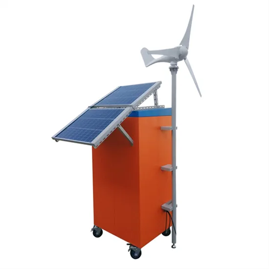
Learn how to wire a 12V solar panel system with this straightforward wiring diagram and step-by-step guide. Wiring a 12V solar panel typically involves connecting the positive and negative
Self-Clinching Locking Nuts provide strong female prevailing torque locking threads in panels that are too thin to be conventionally tapped. Utilising a special proven clinch feature, this fastener
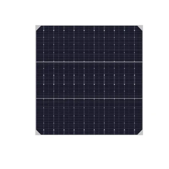
This document provides safety and installation instructions for the UL Listed SunPower AC photovoltaic (PV) modules described herein, all of which bear the UL logo on the product label:
Solar panel diagrams are an essential tool for both the installation and maintenance of solar panel systems. These diagrams provide a visual representation of how the panels are connected and how the energy flows

end with a nut that''s torqued to 20–25 in‐lb (for a #10‐32 bolt). A lock washer or other locking mechanism is required to maintain tension between the bolt and the assembly. The conductor
Solar Panel Installations:In solar panel installations, lock nuts secure mounting hardware, frames, and tracking systems.They maintain the orientation and stability of solar panels for optimal energy generation.
Indoor Installation Outdoor Installation . Locations where the yearly average high temperature. 1. is below 25˚C/77˚F 8" between inverters 8" between inverters 1.2" between inverters (if
Adjust nut in height according to direction of the module carrier rails. Place adapter plate, adjust and mount additional washer with locking nut. The height of the adapter plate is determined by the two nuts. Secure solar fastener against turning with hex wrench. After correct setting of both nuts, lock and tighten.
MOUNTING INSTRUCTIONS PV modules can be mounted to the substructure using either corrosion-proof M8 bolts placed through the mounting holes on the rear of the module or specially designed module clamps. A clearance of at least 115mm(4.5in) (recommended) is provided between modules frame and the surface of the wall or roof.
Trina Solar has tested its modules with a number of clamps from different manufacturers and recommends the use of clamps which have an EPDM or similar insulating washer, fixing bolt of at least M6. The clamp must overlap the module frame by at least 7mm(0.28in) but no more than 10mm(0.39in).
SunPower recommends using one of the following methods of grounding the module frame. A‐Series ‐BLK modules must be installed with the Ground Lug Assembly of the Invisimount mounting system using the Ilsco GBL‐4DBT grounding lug tightened to a torque of 85 in‐lbs to bond the module frame to the rail.
The solar fastener can be drilled, tapped and screwed in one operation using the hardened steel drill tip. Measure the screw distances according to statics or K2 Base. Check position of purlins and pre-drill through the fibre cement profiles into the purlins.
The minimum distance between fastened flat head screws and the edges of rafters and purlins must be three times the flat head screw diameter. Position hanger bolts in the centre of rafters and outside the centre on purlins. * Values are based on crystalline solar modules, the weight of the mounting system increases with thin-film solar modules.