What is a Wiring Diagram for Solar Panels? A wiring diagram for solar panels is a visual representation of the electrical connections and components in a solar panel system. It shows
Here''s a basic diagram to visualize the connections between the components of your solar power setup in your campervan: This diagram shows the flow of electricity from the solar panel, through the charge controller, to the battery,
Even if you don''t do any harm, a smart solar panel wiring plan will optimize performance and maximize the return on your investment. Read on to find out more about solar panel connection diagrams and how to wire PV
It plays a crucial role in ensuring the safety and efficiency of the solar panel installation. The combiner box is responsible for combining multiple strings of solar panels into a single circuit,
Discover the essential components and connections of a wiring diagram for solar panels, including the placement of inverters, charge controllers, and batteries. Learn how to properly wire your solar panel system to maximize efficiency and
The connection diagram for a solar panel and inverter system typically involves the following steps: If the measured voltage is significantly lower than the expected range, it may indicate
Discover the components and layout of a solar panel system through a detailed schematic diagram. Learn how solar panels, inverters, batteries, and other essential components work together to harness the power of the sun and

At the heart of every solar energy system lies the solar panel wiring diagram, a blueprint that maps out the connections between various components such as solar panels, inverters, charge controllers, batteries, and electrical wiring.
What is Pulse Width Modulation Or A PWM Charge Controller? A PWM (Pulse Width Modulation) controller is an (electronic) transition between the solar panels and the batteries:. The solar charge controller (frequently referred to as the
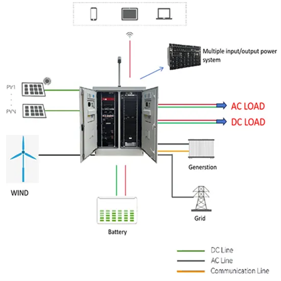
A solar panel system schematic diagram is a visual representation of how the different components of a solar panel system are connected to each other. It shows how solar panels, inverters, batteries, and other components work
The solar panel wiring diagram provides a visual representation of how electrical connections should be made. It shows the correct placement of wires and terminals, which helps prevent any potential hazards such as short circuits.
The wiring diagram outlines the layout and connections for the panels, inverters, batteries, and other components in a solar power system. It provides a visual representation of how the system should be set up and connected to ensure
Learning the basics of solar panel wiring is one of the most important tools in your repertoire of skills for safety and practical reasons, after all, residential PV installations feature voltages of up to 600V. There are three
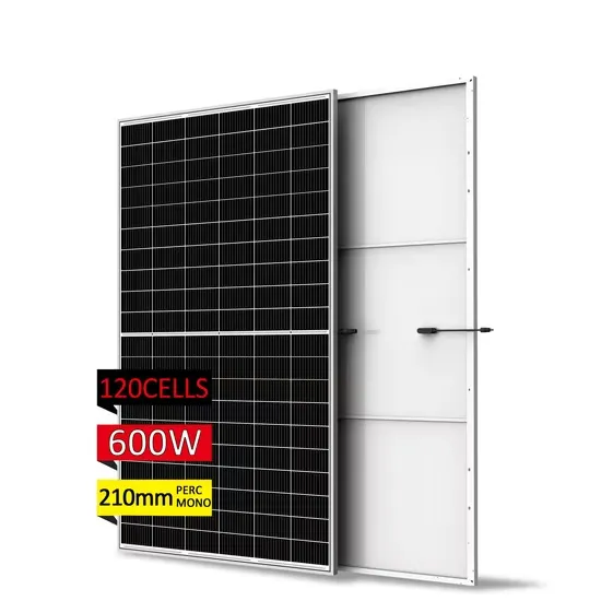
Solar Module Cell: The solar cell is a two-terminal device. One is positive (anode) and the other is negative (cathode). A solar cell arrangement is known as solar module or solar panel where solar panel arrangement is known as
A solar panel wiring diagram (also known as a solar panel schematic) is a technical sketch detailing what equipment you need for a solar system as well as how everything should connect together. There’s no such thing as a single correct diagram — several wiring configurations can produce the same result.
Learning the basics of solar panel wiring is one of the most important tools in your repertoire of skills for safety and practical reasons, after all, residential PV installations feature voltages of up to 600V. There are three wiring types for PV modules: series, parallel, and series-parallel.
The schematic diagram typically starts with the solar panels, which are the main source of the system’s power. The panels convert sunlight into electricity through the use of photovoltaic cells. The diagram shows how the panels are connected in series or parallel to form an array, allowing for maximum energy production.
The diagram will show the appropriate connections for the inverter and battery bank, including the necessary fuses, switches, and disconnects. Grounding and Safety: Another important aspect of the wiring diagram is the grounding system. The diagram will show how the solar panels and other components are grounded to ensure safe operation.
A well-designed wiring system includes the integration of an inverter, which converts DC electricity from the solar panels into AC electricity compatible with the existing power grid. The wiring also incorporates safety measures such as circuit breakers and surge protectors to prevent overloading and electrical hazards.
Wiring: To connect solar panels, a wiring system is used. There are two types of wiring systems commonly used: series wiring and parallel wiring. In series wiring, the positive terminal of one solar panel is connected to the negative terminal of the next panel. This allows the generated voltage to add up, resulting in a higher voltage output.