Components of an On Grid Inverter Circuit Diagram. An on grid inverter circuit diagram consists of various components that work together to convert the direct current (DC) generated by solar panels into alternating current (AC) for use in
Download scientific diagram | Power circuit diagram of an IGBT based single phase full-bridge inverter. from publication: Design and implementation a specific grid-tie inverter for an agent
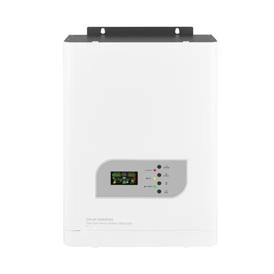
One of the key components in photovoltaic (PV) electrical systems is the inverter. It is the unit that converters the DC power generated from the solar panels or the batteries to an AC power that
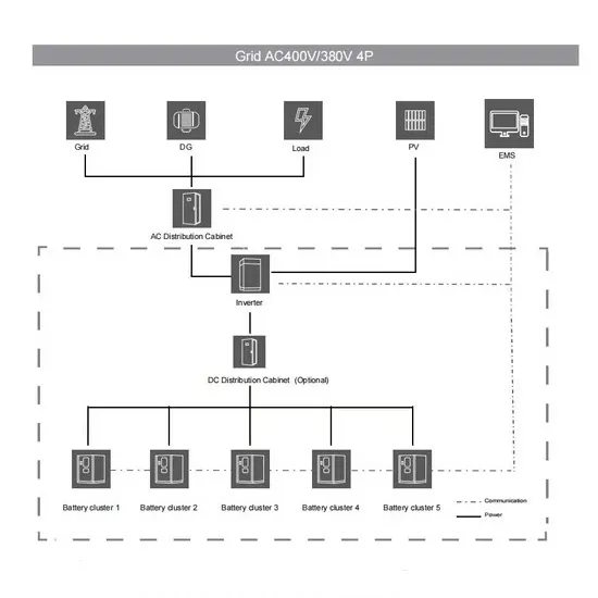
III. PV Control Design Control system is designed in order to control the power generated from the PV system to the grid system. From the block diagram for three-phase grid-connected PV
The aim of this research is to study the micro inverter technology, where the inverter is placed on each photovoltaic (PV) module individually in comparison to the common string or central inverters. In the already existing string and
mode control) or on the inverter output current (Current-mode control). In the last case, i in current is influenced by v in voltage (Fig. 1). Actually, power is controlled by the phase angle and the
3490E. Lawrence Berkeley National Lab.(LBNL)," Berkeley, CA (United States), 2010. • A. Luque and S. Hegedus, Handbook of photovoltaic science and engineering, John Wiley & Sons,
Integrate PV inverters into utility supervisory control and data acquisition systems or AMI systems. Inverters could be tied into utility communications systems, which would issue a warning to inverters in sections of the utility isolated from the mains. Any available channel, such as BPL, DSL, or coax, could be used.
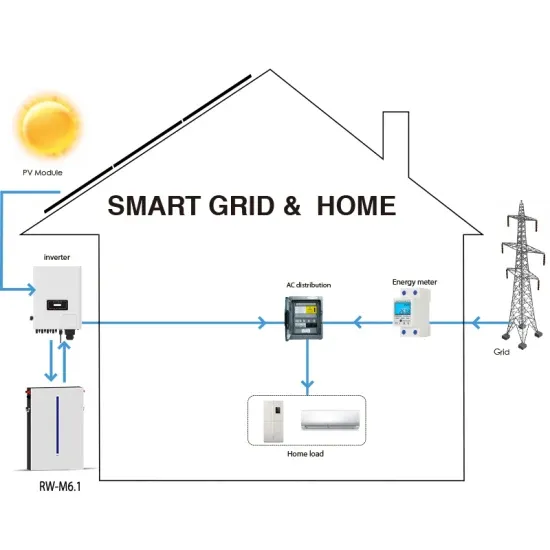
The document provides the minimum knowledge required when designing a PV Grid connect system. The actual design criteria could include: specifying a specific size (in kWp) for an array; available budget; available roof space; wanting to zero their annual electrical usage or a number of other specific customer related criteria.
The solar panel or PhotoVoltaic (PV) panel, as it is more commonly called, is a DC source with a non-linear V vs I characteristics. A variety of power topologies are used to condition power from the PV source so that it can be used in variety of applications such as to feed power into the grid (PV inverter) and charge batteries.
Identify inverter-tied storage systems that will integrate with distributed PV generation to allow intentional islanding (microgrids) and system optimization functions (ancillary services) to increase the economic competitiveness of distributed generation. 3.
A PV inverter or the power conditioning systems of storage within a SEGIS could provide voltage regulation by sourcing or sinking reactive power. The literature search and utility engineer survey both indicated that this is a highly desirable feature for the SEGIS.
A typical PV grid tied inverter uses a boost stage to boost the voltage from the PV panel such that the inverter can feed current into the grid. The DC bus of the inverter needs to be higher than the maximum grid voltage. Figure 20 illustrates a typical grid tied PV inverter using the macros present on the solar explorer kit. Figure 20.