(a) Wind tunnel test model diagram (b) Wind direction definition Fig. 1. Wind tunnel test model diagram A total of 240 measurement points were arranged on the photovoltaic components.
As already noted in Section 3, it is recommended that the nett uplift wind pressure on panels be calculated using the largest peak negative (uplift) aerodynamic shape factor value (C fig =
The analysis shows for the load from wind and snow that the structures on a sloping roof have with relatively the least load, and the structures on a flat roof - with the highest (due to the
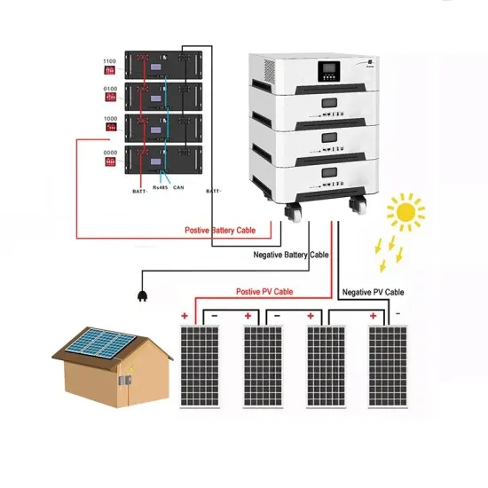
Fig. 3. Diagram of the seven operating positions of the photovoltaic panel The geometric model shown in Fig. 1, is built of profiles (Fig. 2) and a surface recreating the solar panel. Steel
photovoltaic (PV) solar system is designed, tested and installed to resist the wind pressures that may be imposed upon it during a severe wind event such as a thunderstorm or cyclone whilst
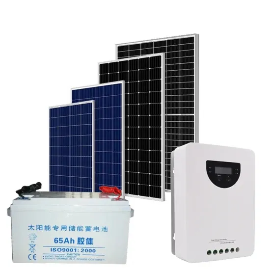
panel facing overheating. This result to solar panel produced less power output. It is also found that performance of solar panel is very sensitive to its operating temperature. The heat energy
tovoltaic (PV) solar systems in typical applications, when mounted parallel to roofs.2 SCOPEThis document applies to the testing of the structural strength performance of photo voltaic solar systems to resist simulated wind loads when installed on residential roofs, where the panels are installed parallel to the roof surface
Jubayer and Hangan (2014) carried out 3D Reynolds-Averaged Navier–Stokes (RANS) simulations to study the wind loading over a ground mounted solar photovoltaic (PV) panel system with a 25 ° tilt angle. They found that in terms of forces and overturning moments, 45 °, 135 ° and 180 ° represents the critical wind directions.
Stenabaugh et al. (2015) studied the effects of geometric dimensions on the wind loads acting on roof-mounted PV panels via wind tunnel tests and found that both larger gaps between panels and smaller gaps between the panel and roof surface can produce lower wind loads.
dard also considers the effects of wind loading on PV arrays including the mounting system. This technical note further highlights the consideration that should be made to ensure that a photovoltaic (PV) solar system is designed, tested and installed to resist the wind pressures that may be imposed upon it during a severe w
In order to quantify the aerodynamic loading on the panel’s structure, extensive experimental tests were performed using a wind tunnel. Once the critical wind directions and panel inclinations were determined, a numerical analysis of the structural components was performed.
It is important to note that when the upper and lower rows of PV panels align with the wind direction at 0° and 180°, the wind pressure coefficients are close to 0, rendering the analysis of uneven wind pressure coefficients for these directions unnecessary.