Step 2e: Calculate the solar panel output under the given conditions. C Impp × STC Vmpp Pmax (W) = Voc × Isc × STC Isc × STC Voc9. ×9.75 A × 39.6 VStep 2f: Calculate the maximum
A diverted PV system uses an intelligent control box to divert "spare" solar electricity from your solar PV panels into a conventional hot water tank. So, electrically it is about four times less
Mounting: Securely mount the PV combiner box close to the solar panels.. Connections: Connect the positive and negative terminals of the solar panels to the corresponding inputs in the combiner box.. Safety Devices:

To meet the requirements of the DOE Zero Energy Ready Home program, provide an architectural drawing and riser diagram of RERH solar PV system components and solar hot water. Develop architectural drawings and
The design of such a system is very simple as we have to match the power and voltage rating of the PV module to that of the DC pump motor so when the module receives the solar radiation the pump will draw the water and store it
The solar heating system drawings show examples of various heating design configurations. Each solar water heating design is available as a complete DIY kit. Each design is pre-engineered for maximum performance and safety. You can
Provide an architectural drawing and riser diagram for the homeowner showing the planned location for future solar hot water and photovoltaic system components. Space requirements and layout for solar water heating and photovoltaic system components should be taken into account early in the design process.
When designing a solar pumping system, the designer must match the individual components together. A solar water pumping system consists of three major components: the solar array, pump controller and electric water pump (motor and pump) as shown in Figure 1.
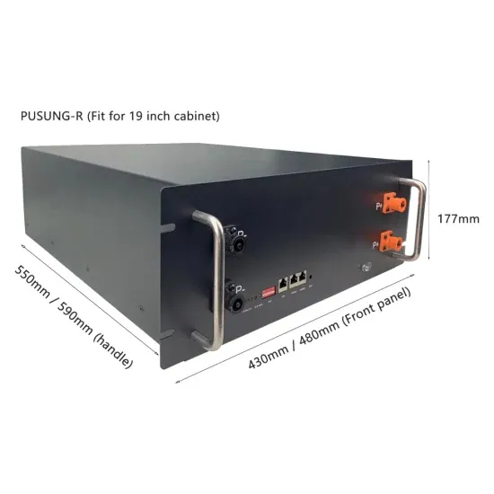
1. Solar Panel The solar panel used in the construction of the solar array must match the nominal rating and specifications selected during the design (see 4.1.1. Solar Panel Selection). Use of an alternate solar panel shall only be permitted with approval of the design engineer of record on the project.
As discussed in 2.2.6. Design Demand, the daily water demand on the solar powered water system alone will be critical to the design of the system. In other words, the water collected from other sources should not be counted in the design demand upon which the system design will be based.
The designer should initially use pipe that is the same size as the inlets and outlets. The designer then undertakes the frictional loss calculations for that size of water pipes using the known maximum water flow for that solar water pumping system.
The specific data would be the size of the inlet and outlet that the water pipe would be connected to. Figure 14 a, b and c shows key dimensions of the three water pumps shown in Figure 13 and used in the solar water pumping systems used in Table 7. The designer should initially use pipe that is the same size as the inlets and outlets.