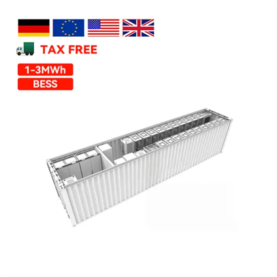
An autonomous PV system operates without a connection to the electrical grid, using photovoltaics as the main source of supply and battery banks for continuous and uninterruptable power supply to
The topology that brings a low-voltage photovoltaic panel that can be connected to the power grid via an inverter using a DC/DC high-gain converter, which has a special feature of controlling
To better understand IAM, read How Radiation and Energy Distribution Work in Solar PV. Figure 3 - Example of I-V curve of a PV module. Image courtesy of PVEducation. Inverter Conversion Bridge . Next, we find
where v s and i s are the grid voltage and current, respectively. v ab denotes the output voltage of the CHB inverter. v pvi and i pvi represent the DC capacitor voltage and output current of the PV strings, i ci is the output
In the present work, simulation of a three-phase H-bridge voltage source inverter (VSI) is designed in MATLAB/Simulink platform. An LC filter is used to reduce the harmonic content of the inverter
Download scientific diagram | The Full H-bridge single phase inverter. from publication: Design and implementation of a pure sine wave single phase inverter for photovoltaic applications |
This paper presents the design of a sine wave inverter (SWI) for photovoltaic (PV) applications. A dc-dc forward converter, an inverter power circuit, a switching control circuit and an immittance
Download scientific diagram | Circuit architecture of a single-phase photovoltaic full-bridge inverter. from publication: Online Control of Smart Inverter for Photovoltaic Power Generation Systems
Fig. 1 shows the power circuit diagram for a single phase bridge voltage source inverter. Four switches (in two legs) are used to generate an AC waveform at the output from the DC source.
What is a Full Bridge Inverter ?. Full bridge inverter is a topology of H-bridge inverter used for converting DC power into AC power.The components required for conversion are two times more than that used in single phase Half bridge
The following paper presents a newly developed transformer-less grid-tie pure sine wave inverter (GTI) for photovoltaic (PV) application. The proposed topology employs a PV panel, a dual
A typical PV grid tied inverter uses a boost stage to boost the voltage from the PV panel such that the inverter can feed current into the grid. The DC bus of the inverter needs to be higher than the maximum grid voltage. Figure 20 illustrates a typical grid tied PV inverter using the macros present on the solar explorer kit. Figure 20.
Between the CCM and VCM mode of VSI, the CCM is preferred selection for the grid-connected PV systems. In addition, various inverter topologies i.e. power de-coupling, single stage inverter, multiple stage inverter, transformer and transformerless inverters, multilevel inverters, and soft switching inverters are investigated.
In this topology, the integration of inverter and PV module is carried out in a single electrical device. It is a “plug and play” device and does not require expertise for its installation. The mismatch losses of the PV modules are eliminated in this topology . It has a modular design and can be easily expanded.
The inverter state machine then sequences to checking for DC voltage. To feed current into the grid the DC voltage (which in case of PV inverters is provided from the panel or panel plus some conditioning circuit), it must be greater than the peak of the AC voltage connected at the output of the inverter.
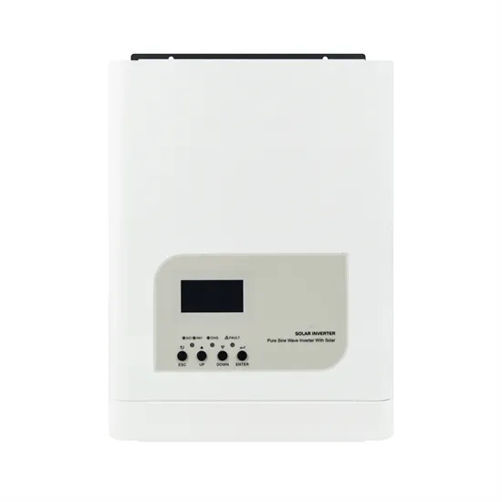
Electrical production from photovoltaic panels (PV) gives DC voltage. So, the use of inverters is a compelling solution to convert the output voltage to the alternative form. The increase of the electric power, in stand-alone or grid-connected PV systems, leads to increase in the switched current.
In order to couple a solar inverter with a PV plant, it’s important to check that a few parameters match among them. Once the photovoltaic string is designed, it’s possible to calculate the maximum open-circuit voltage (Voc,MAX) on the DC side (according to the IEC standard).
