The main components of a wind turbine electrical schematic include the generator, the control system, the power electronics, and the grid connection. The generator is responsible for converting the mechanical energy from the
These panels provide real-time monitoring of your power systems, so you can quickly detect any outages or other issues. Understanding the wiring diagrams associated with these panels can help you ensure that
In summary, this circuit matches a low voltage solar or wind turbine input to a higher voltage battery. An analogue circuit will measure incoming current and voltage inputs to set the maximum power point tracking

In addition to the turbine, the wind power schematic diagram will also include the generator. This is the device that converts the mechanical energy of the turbine into electrical energy. Generators come in a variety of sizes and
Instead of winding a vertical axis wind generator yourself, a simpler idea would be to configure the VAWT mechanism with a high watt generator or a dynamo through a correctly calculated gear or pulley/belt ratio.
An effective circuit diagram of a synchronous generator is essential for efficient power generation. It is used to ensure that the generator produces electricity at the desired voltage and current levels, and is able to

Craftsman 580 325600 1796 0 5 600 Watt Portable Generator Wiring Diagram Parts Lookup With Diagrams Partstree. Small Sel Generators Wiring Diagrams. Briggs And Stratton Power Products 1933 1 6 500 Watt Pro

At its most basic level, a wind turbine circuit diagram consists of four main elements: the turbine tower, the blades, the generator, and the inverter. The tower is the main structural element that supports the weight of the
The wind turbine circuit diagram is an invaluable tool for understanding how turbine-powered electricity is created. By mapping the system’s components and wiring, a typist can easily understand the flow of energy from the turbine to the power transformer and then to the actual grid.
The main components of a wind turbine electrical schematic include the generator, the control system, the power electronics, and the grid connection. The generator is responsible for converting the mechanical energy from the spinning blades into electrical energy.
Wind generator wiring diagrams can vary depending on the type of machine and its design. For example, some machines feature multiple blades while others have a single blade. A turbine’s operational characteristics can also affect the type of wiring diagram that should be used. The most common type of wiring diagram is the one-line diagram.
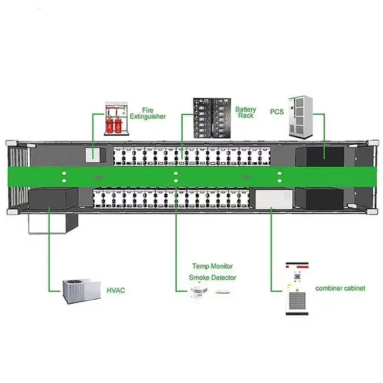
Wind Turbine Generator: This is the primary component responsible for converting wind energy into electrical energy. It consists of a rotor with blades that spin in response to the wind, which in turn rotates a shaft connected to a generator.
The schematic diagram typically includes labels and symbols to identify each component and its function. It shows the main parts of the turbine, such as the rotor blades, the gearbox, the generator, and the tower. It also illustrates the flow of energy and the movement of mechanical parts within the system.
3.2 Procedures to assemble the wind turbine generator. for 3KW & above models) from the tower bottom to the tower end by using the thin steel wires. Hang up the wind generator by crane or chain block together with triple-angle stand. Make sure the section. (three-phase wires, without identifying positive and negative electrodes). turbine”.