(Source: Electrical Technology) By combining parallel and series connections in a hybrid wiring configuration, you can address issues like shade and high voltage to maximize your electricity output and performance..
Photovoltaic system diagram: components. A photovoltaic system is characterized by various fundamental elements:. photovoltaic generator; inverter; electrical switchpanels; accumulators. Photovoltaic
All about Solar Panel Wiring & Installation Diagrams. Step by step PV Panel installation tutorials with Batteries, UPS (Inverter) and load calculation. Breaking News. 50% OFF on Pre-Launching Designs - Ending Soon ; How to Wire
In the diagram above, the output voltage of each panel is 6 volts. If you''re worried about the current being too low, consider wiring the four PV panels in parallel. With a four-panel array, there''s no benefit to wiring it in
It provides a clear and systematic guide for wiring connections, fusing, and grounding. Following the diagram will help ensure the safety, efficiency, and long-term performance of your solar
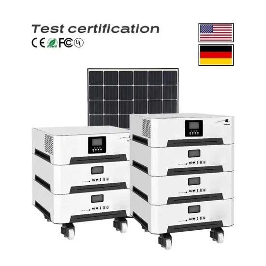
However, to truly harness the potential of solar energy, connecting the solar panels to an inverter is essential. The inverter serves as the heart of the solar power system, converting the direct
This article provides a comprehensive guide on wiring solar panels in parallel, including a detailed diagram to help you visualize the setup. Wiring solar panels in parallel involves connecting multiple panels together in a way that maintains

There are three wiring types for PV modules: series, parallel, and series-parallel. Learning how to wire solar panels requires learning key concepts, choosing the right inverter, planning the configuration for the
This tutorial contains step-by-step instructions on wiring solar panels in series and parallel. You''ll learn: How to wire solar panels in series. How to wire solar panels in parallel. The differences between series vs parallel
Create detailed documentation of your solar panel wiring diagrams, including equipment specifications, wiring diagrams, and installation instructions. Ensure that your design complies with local building codes, electrical regulations, and
See a complete example solar panel wiring diagrams done by Ecuip Engineering & Solar Design Lab here: Download Example Solar Panel Wiring Diagram. Understanding Solar Panel Wiring Diagrams. At the heart of every solar
Typically, microinverter PV modules are available in series or parallel connection options. Because of how the panels are constructed, you can’t switch a microinverter panel from series to parallel just by changing the wiring between terminals from module to module.
A solar panel wiring diagram (also known as a solar panel schematic) is a technical sketch detailing what equipment you need for a solar system as well as how everything should connect together. There’s no such thing as a single correct diagram — several wiring configurations can produce the same result.
For example, if wiring 3 solar panels in parallel, use a pair of 3 to 1 branch connectors. And if wiring 4 solar panels in parallel, use 4 to 1 branch connectors. Note: When wiring solar panels in series, I showed you how to confirm that they were correctly wired by checking the open circuit voltage of the 2-panel string with a multimeter.
Wiring solar panels in series sums the voltages, but the current remains the same. Wiring solar panels in parallel sums the currents, but the voltage remains the same. Note: You can calculate the power output of your series and parallel wiring configurations with our solar panel series and parallel calculator.
Connecting PV modules in series and parallel are the two basic options, but you can also combine series and parallel wiring to create a hybrid solar panel array. Some solar panels have microinverters built-in, which impacts how you connect the modules together and to your balance of system. What Are They?
In large PV plants first, the modules are connected in series known as “PV module string” to obtain the required voltage level. Then many such strings are connected in parallel to obtain the required current level for the system. The following figures shows the connection of modules in series and parallel.